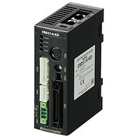
5 Phase Stepper Motor Driver Projects
For this project i am going to use bipolar stepper motor. The name of motor is NEMA 17. It is commonly used in 3D printers and is popular among diy circuit makers. Its a 2 phase 4 wire stepper motor. It consumes 1 amperes to 1.5 amperes of current. Voltage requirements are 2.4 volts minimum. Step angle is 1.8 degrees. In this paper, an intelligent five-phase stepping motor driver of. Keywords:five-phase hibrid stepper motor; PWM, N-channel MOSFET array; sequencer; dedicated IC. All project goals were achieved in this step motor driver design.
Selectable Step Angle and Run Current Control The CVD driver has a step resolution switch to allow for matching the input pulse frequency of the controller. Simply use the step angle setting switch to set the input pulses desired. Output pulses are theoretical values as the Smooth Drive feature ensures maximum step performance operation of the stepper motor. The Smooth Drive microstepping control will still be utilized.
Smooth Drive is a function to achieve lower vibration and noise at low speed operation without changing the step angle setting. This function divides the step angle automatically in response to the pulse signals. There is no need to change the setting of the pulse signals (speed, number of pulses) on the controller side. Set the smooth drive function with the OFF/SD selection switch.
Run Current The motor current for when inputting pulses (operating current) can be changed with the RUN Current switch. If the load is small and there is an ample allowance for torque, motor temperature rise can be suppressed by setting a lower operating current. The operating current is a value in which the operating current rate is multiplied by the rated current (100%). Minimum current is 25% of rated and selectable in 5% increments. The CVD Driver can also be used with lower amperage stepper motors. Use the Run Current Selection Switch to match the motor current ratings. Standstill Current When the motor stops, the current cutback function will be actuated to lower the motor current to the standstill current.
The driver standstill current rate can be switched between 25% and 50% using the STOP switch. When setting the switch to the OFF side, the standstill current rate will be set to 25%. Then setting the switch to the ON side, the standstill current rate will be set to 50%. Alarms Monitor the driver performance for early detection of any abnormalities. All CVD drivers have built in alarms to alert when there is a problem. The alarms are both a blinking LED and an Alarm signal to an upper controller.
Alarms range from Overheat, Overvoltage, Overcurrent to EEPROM error and CPU error.
Basically there are two types of stepper motors: bipolar and unipolar. The bipolar stepper motor is a two-phase brushless motor which has two coils (windings), this motor has 4 wires (2 wires for each coil). The other type is the unipolar stepper motor, it is 4-phase brushless motor which has 5 or 6 wires.
The popular controlling modes of of the stepper motor are: full step and half step. The full step can be divided into 2 types: one-phase and two-phase. In full step one-phase mode the driver energizes one coil at a time. This type of controlling requires the least amount of power but provides the least torque.
Term-PRO Enclosure Design Software Download. DBDRA 1X Event Listing. Term lab software cracked download.
Descargar MS Project 2010 Gratis Full Felix Samora. Descargar e Instalar Ms Project full. Microsoft Office Professional 2016 Full Download & Activation For Free. Descargar microsoft project 2010 gratis completo full espaol para.
In full step two-phase mode the driver energizes the two coils at the same time. This mode provides the highest torque but it requires twice as much power as one-phase mode. Half step mode is a combination of the two full step modes (one-phase and two-phase). This mode increases accuracy by dividing each step by 2.

It requires power in-between one-phase and two-phase modes, torque also is in-between. There is another controlling type called microstepping, this type is more accurate than the half step mode, it requires two sinusoidal current sources with 90° shift.